
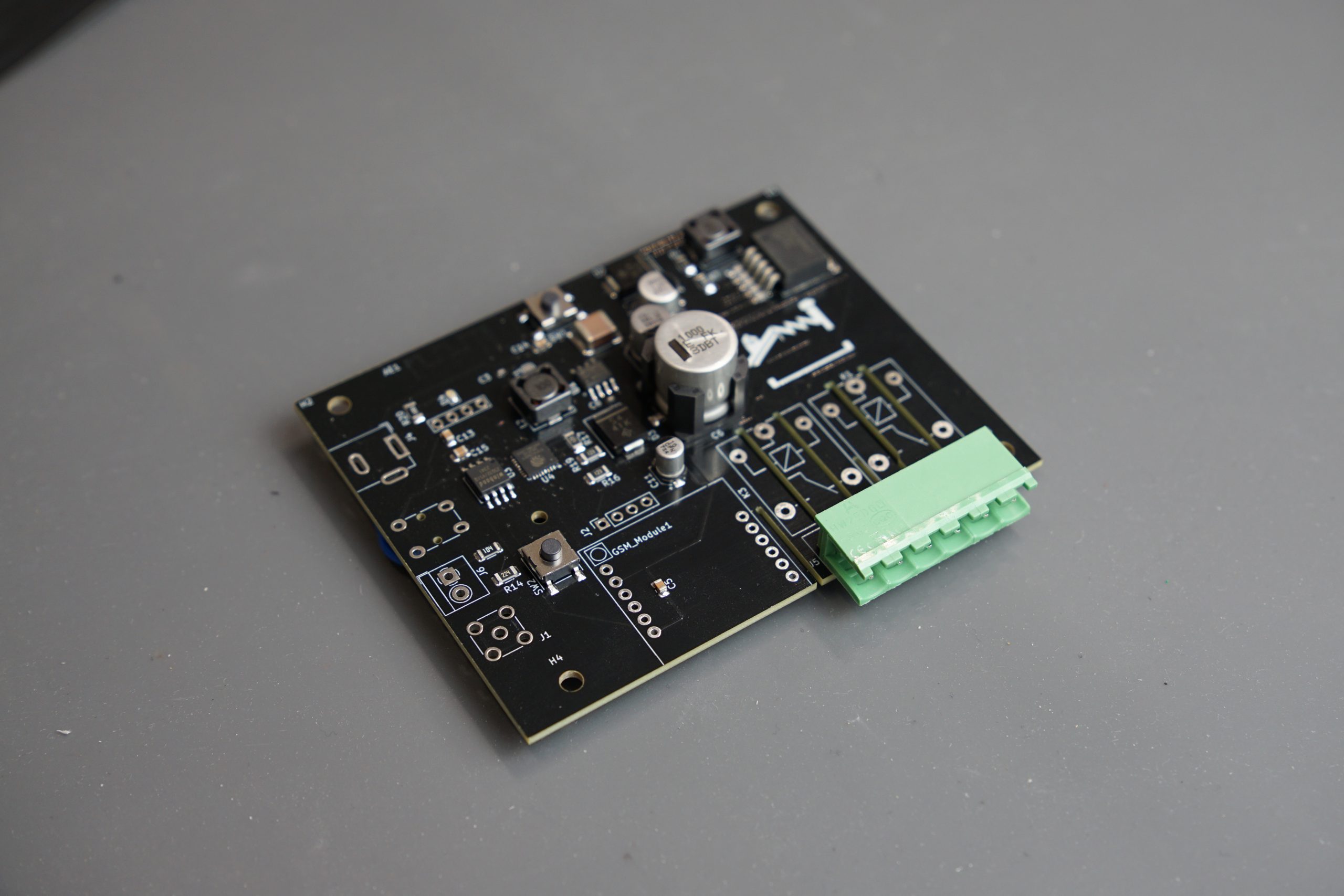
Since publishing the introductory article on “Industrial IoT Applications”, much has evolved. We’ve transitioned to a more modern approach, embracing SMD-based components and compact PCB designs that shift most of the assembly work to the PCB manufacturer. The entire board architecture has been reengineered to support smaller devices within tighter enclosures, without compromising performance.
Just as importantly, the firmware has been optimized for reliable time scheduling and robust communication with web servers over mobile networks, even in remote locations without Wi-Fi access. Join me on this journey as I share the updated process of designing an IoT device built for real-world industrial applications.
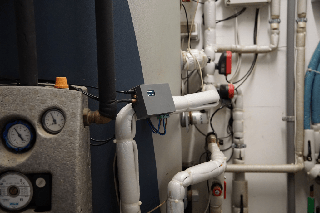
The device functions as a remote control unit designed to schedule the digital state (e.g., on/off) of two outputs based on a programmable weekly timetable with minutes-level precision and to retrive the state of several temperature sensors. It is intended for deployment in remote thermal plants, where the only available communication channel is the mobile network. This constraint necessitates the use of specialized LTE modules, which in turn require careful attention to antenna placement and power supply design.
To simplify user interaction and avoid direct communication with individual devices, the system is integrated with a cloud-based server. This backend manages the real-time status of all connected units and acts as a centralized control layer. Users can configure and monitor their devices through a custom web interface, providing an intuitive and scalable way to manage multiple installations from a single dashboard.
Firmware
The firmware powering this device is engineered for reliability, efficiency, and autonomous operation. It controls input readings and output behavior using a configurable scheduling system that supports multiple time slots for each output. These schedules are automatically validated to prevent overlaps and logical conflicts, ensuring that industrial operations run safely and predictably. Designed for long-term deployment, the firmware handles its own timekeeping and state transitions, requiring minimal user intervention once configured.
A key strength of this firmware lies in its ability to communicate over mobile networks, making it ideal for remote environments where Wi-Fi is not available. Data exchanges with the central web server, such as temperature readings, output states, and system timestamps, are performed using compact, compressed messages. This drastically reduces bandwidth usage and mobile data consumption, helping to minimize operational costs over time. The firmware also incorporates retry mechanisms to ensure that data is reliably delivered even in areas with unstable signal coverage.
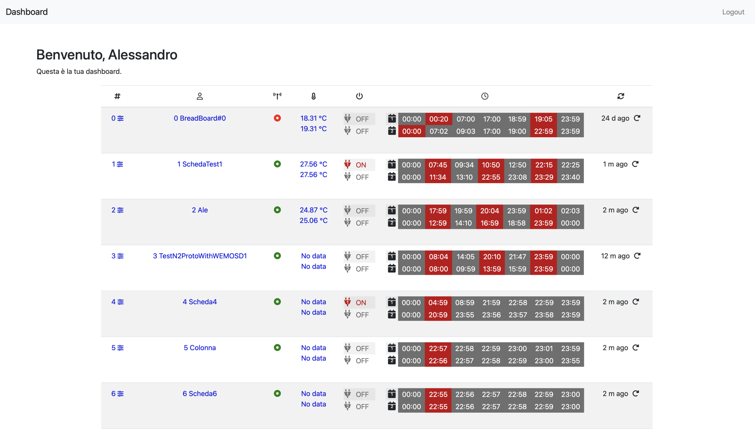
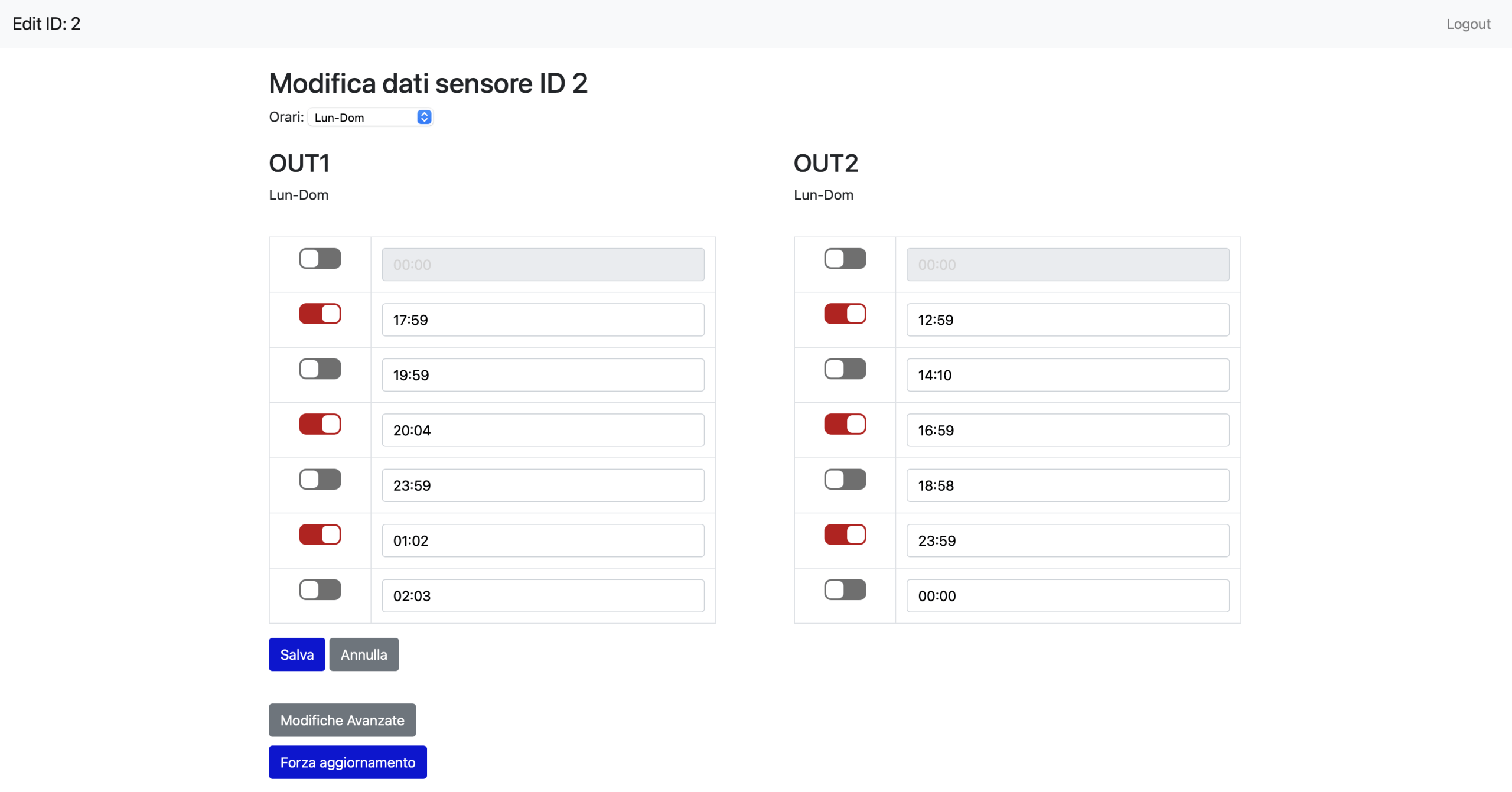
This communication model supports full integration with a remote web dashboard, where users can monitor device activity, analyze historical data, and push configuration updates in real time. By compressing payloads and minimizing unnecessary traffic, the system remains responsive and cost-efficient, even at scale. The result is a self-sustaining, remotely manageable IoT device that’s purpose, built for industrial deployment, capable of adapting to changing environments while keeping both data flow and operating costs under control.
Prototyping and testing
With the core design and firmware in place, we now move into the prototype and testing phase, where the device takes physical form through through-hole assembly, real-world validation, and iterative code refinements to ensure reliable performance in industrial environments.
PCB layout
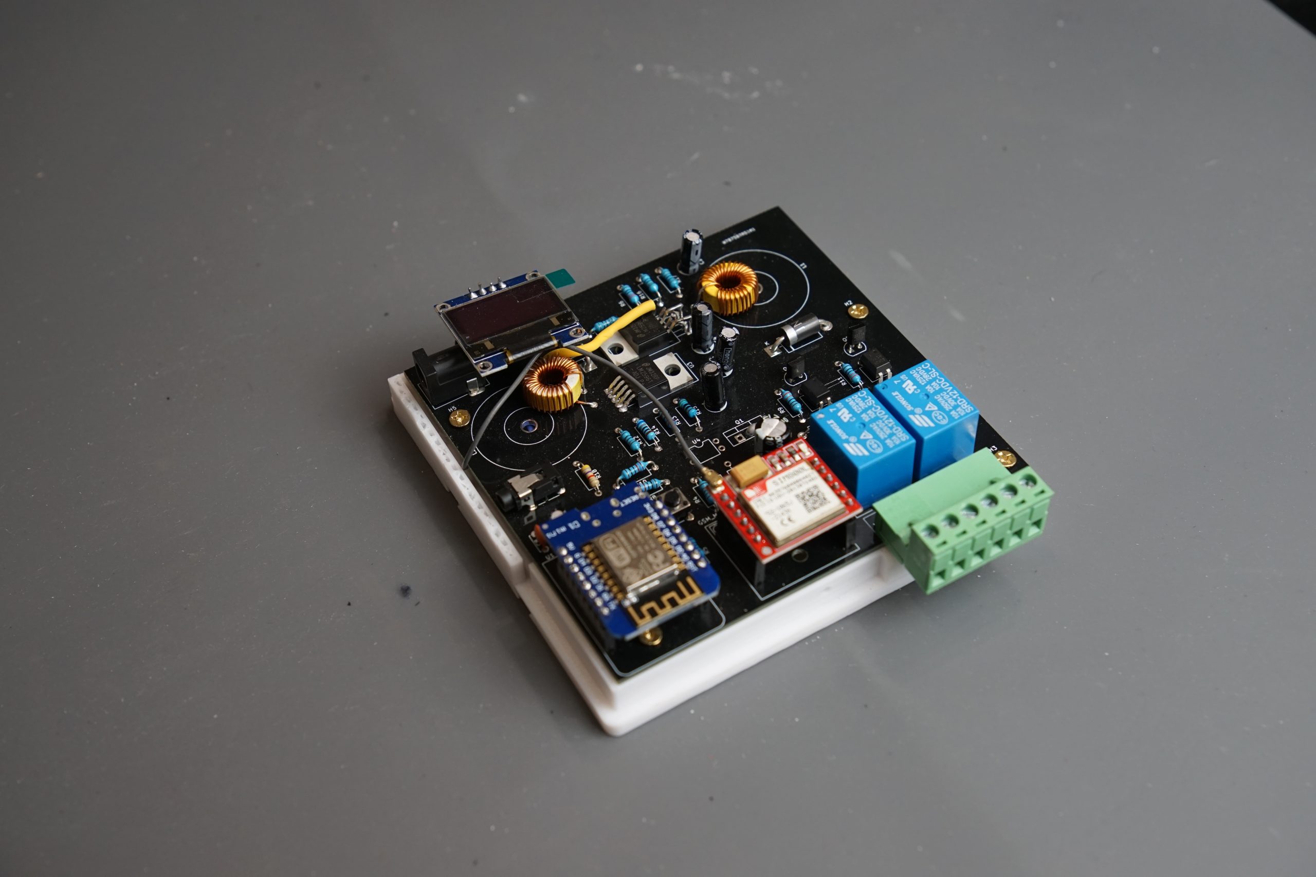
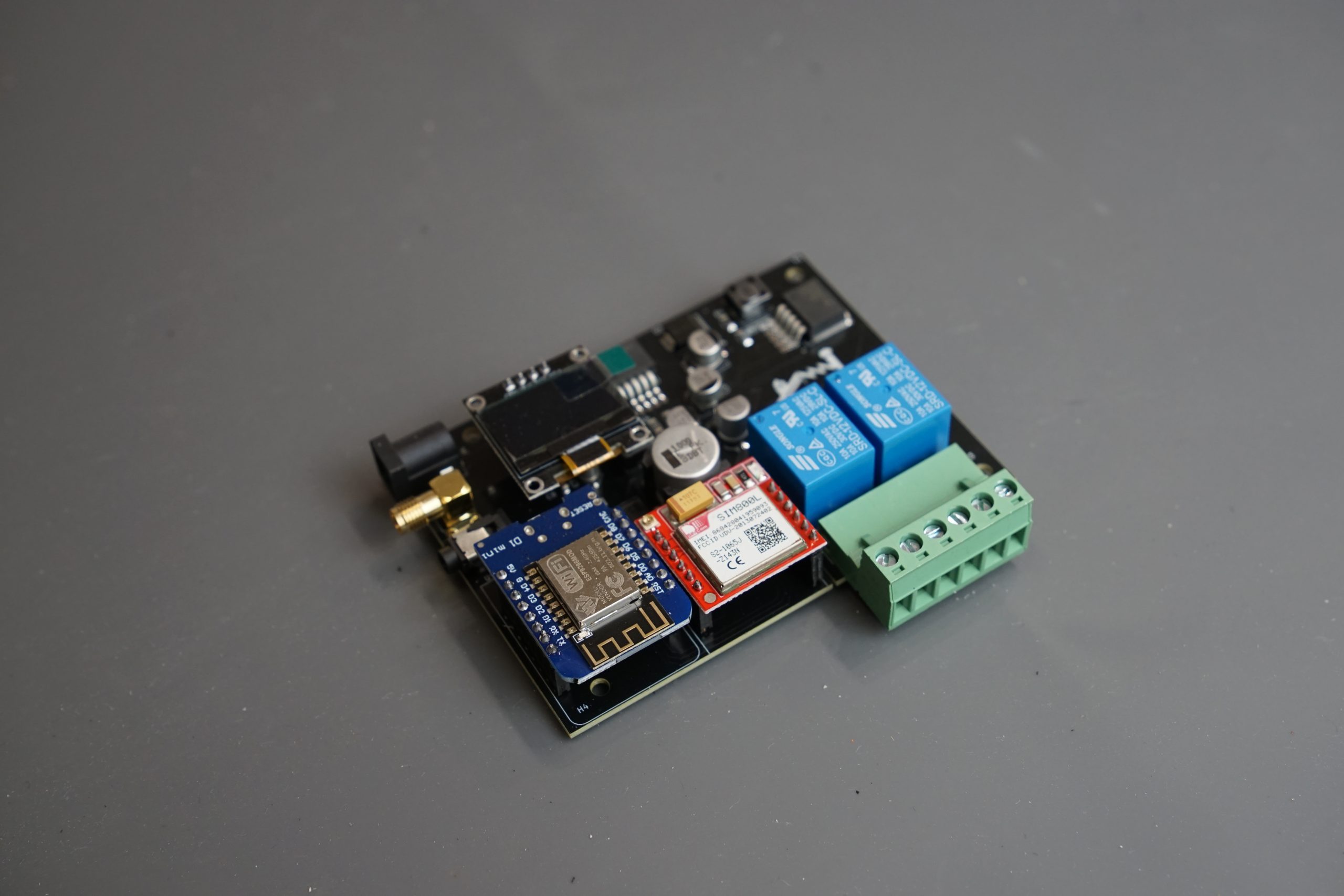
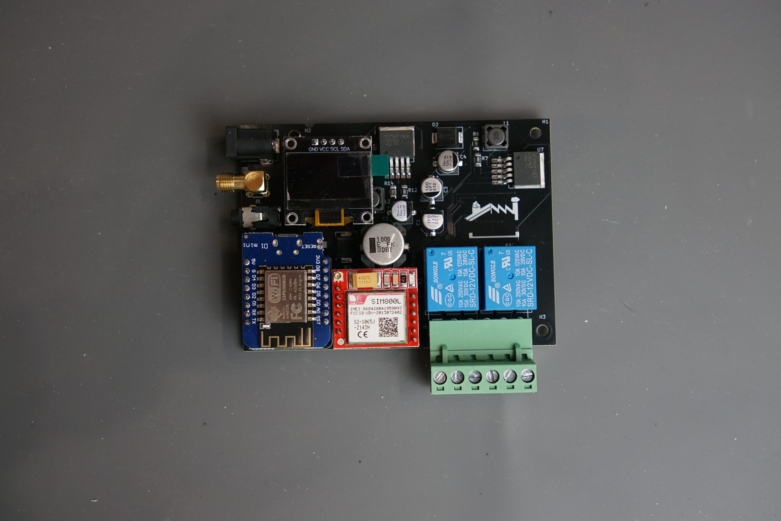
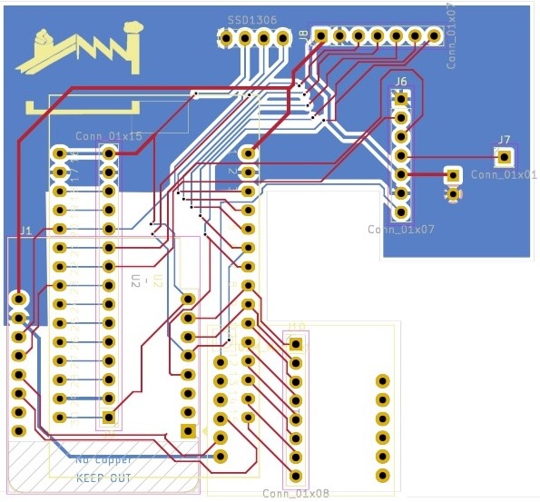
This schematic outlines a compact and modular industrial IoT device designed for remote deployment with mobile network connectivity. At its core is a microcontroller connected to digital and analog inputs, likely for sensors, and GPIOs driving external outputs. The power section includes voltage regulation and decoupling, ensuring stable operation even in noisy environments. The power module handles the conversion of the 12V/3A input into two regulated outputs: 4.8V for the communication module and 5V for the main controller. The main controller then steps down to 3.3V logic for sensor interfacing, while the relays operate directly on the 12V input, controlled via logic-level transistors. Communication is handled via a GSM cellular module, with signal lines and power domains properly interfaced.
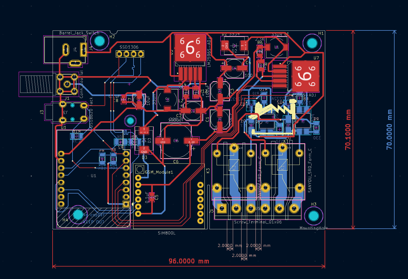
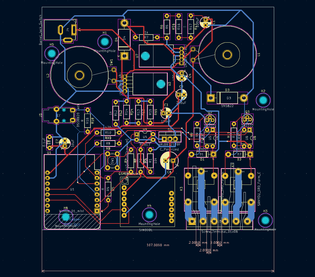
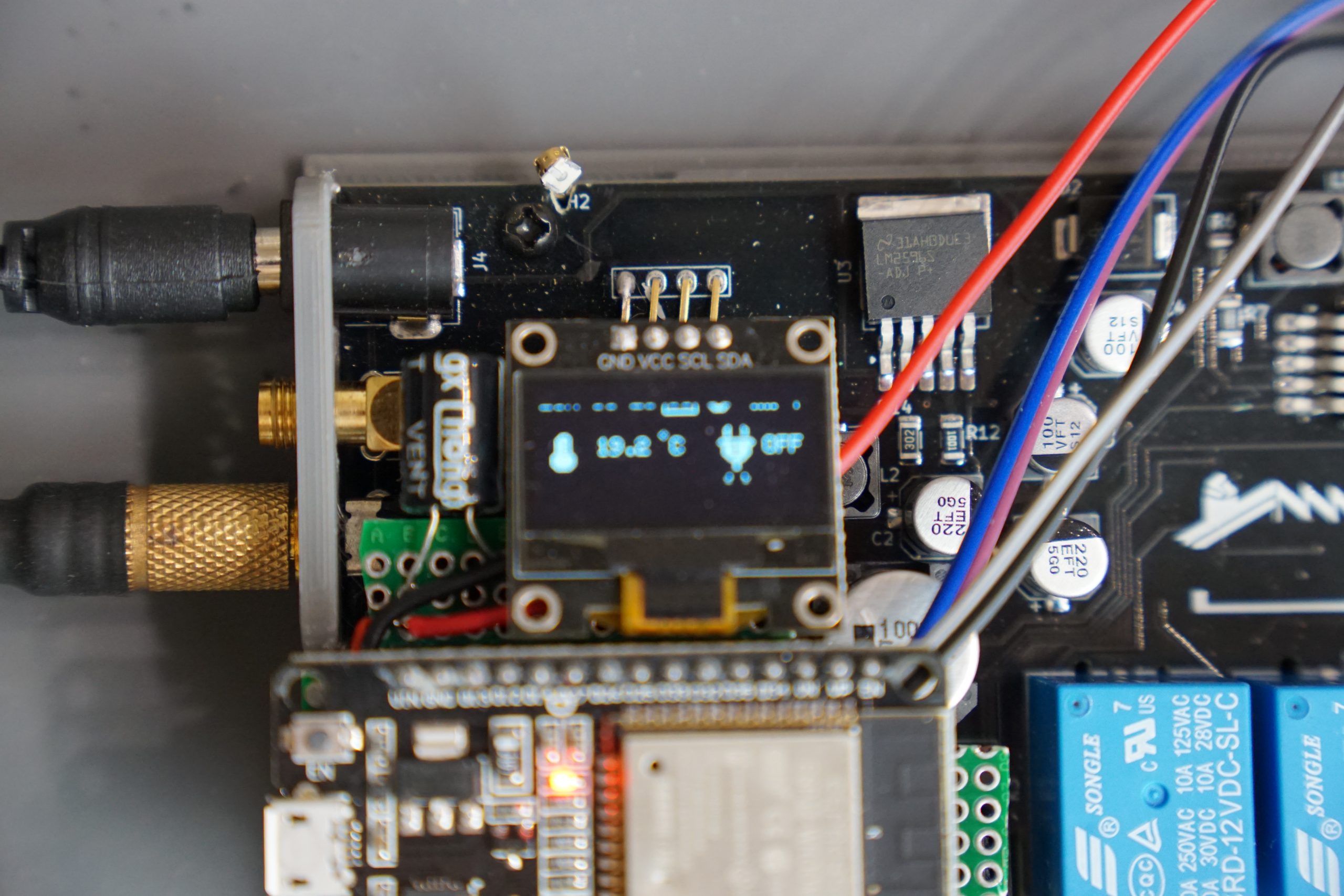
A display interface is present for local feedback, and attention has been given to signal integrity, grounding, and ESD protection. The design emphasizes efficient layout, robustness, and field-ready functionality suitable for industrial automation or monitoring applications.
OLED 64x128 display design.
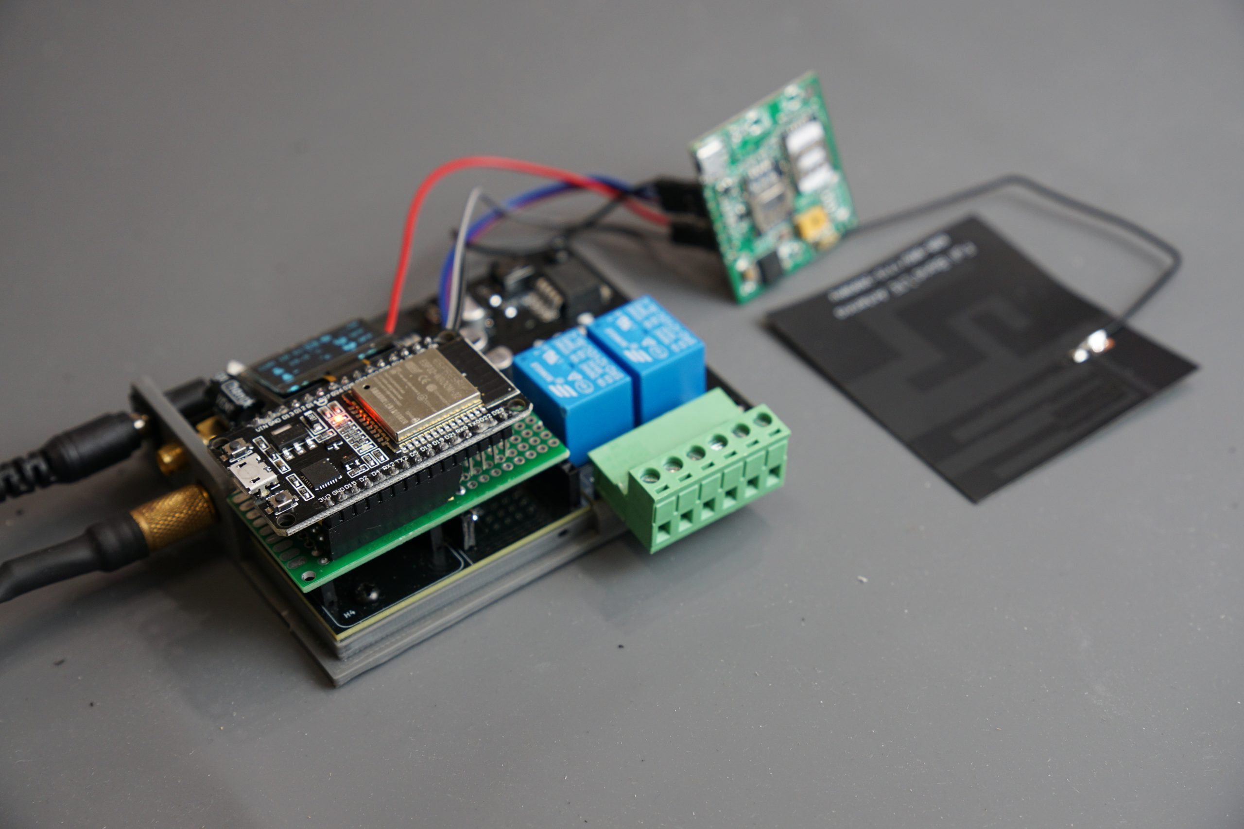
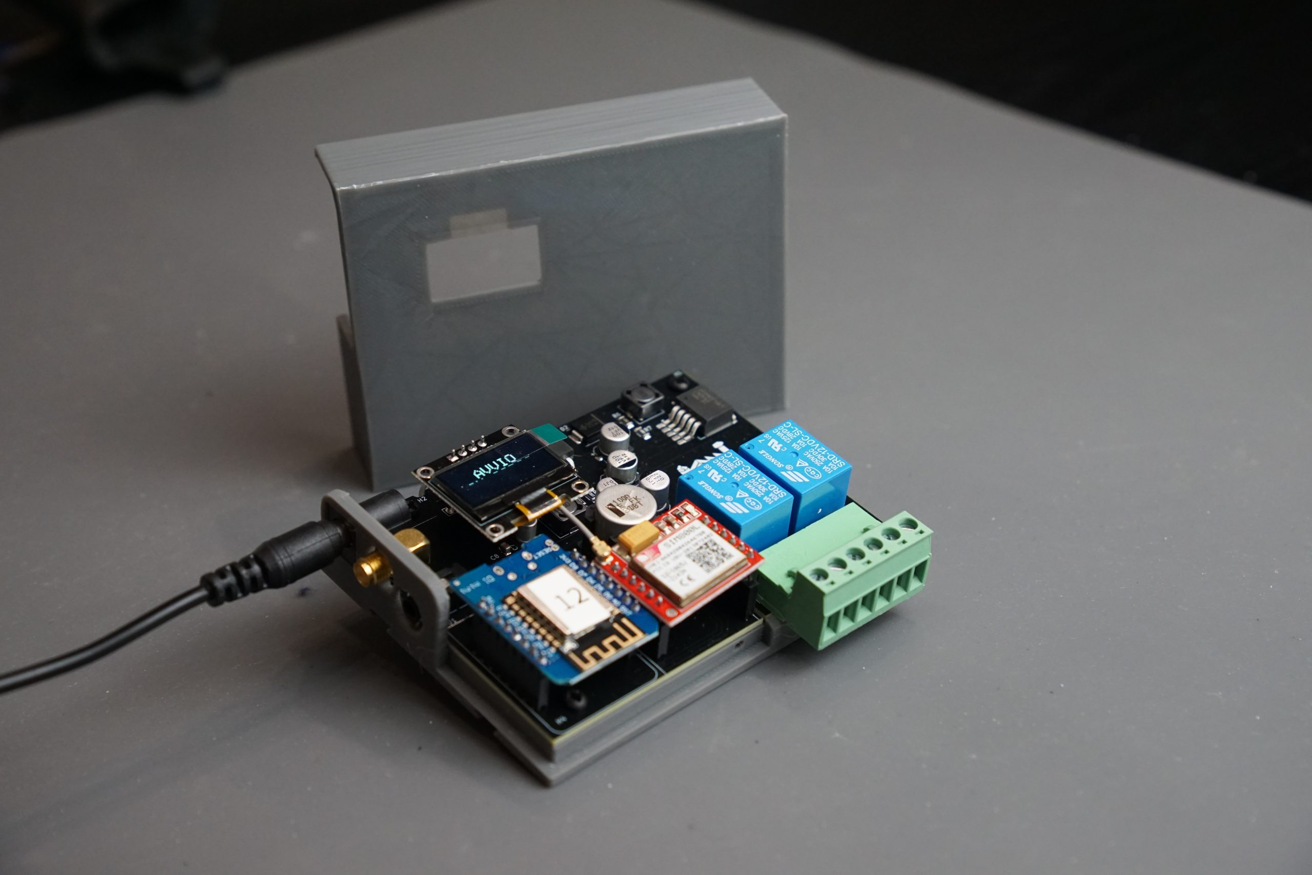
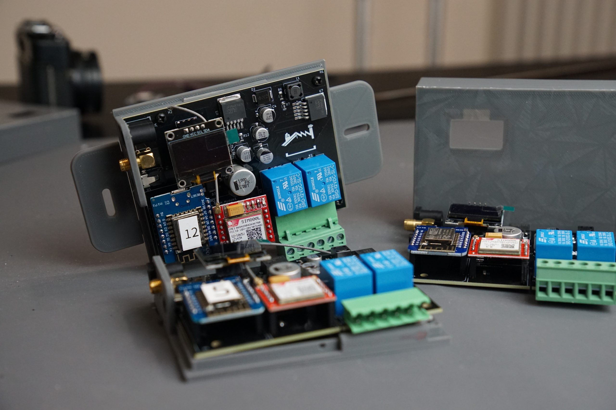
The board still includes some external, pre-assembled modules such as the SIM800L and Wemos D1. This design choice serves two key purposes. First, it facilitates further testing and flexibility during the prototyping phase. Second, it allows for easy replacement or upgrading of individual components, such as updating firmware or swapping damaged modules, without the need to replace or disassemble the main board.
Given that the device is intended for use in industrial and relatively remote environments, this modular approach ensures faster maintenance and improved serviceability. It allows field technicians to access and replace critical modules quickly, minimizing downtime and avoiding the need to handle the entire base hardware.
Enclosure
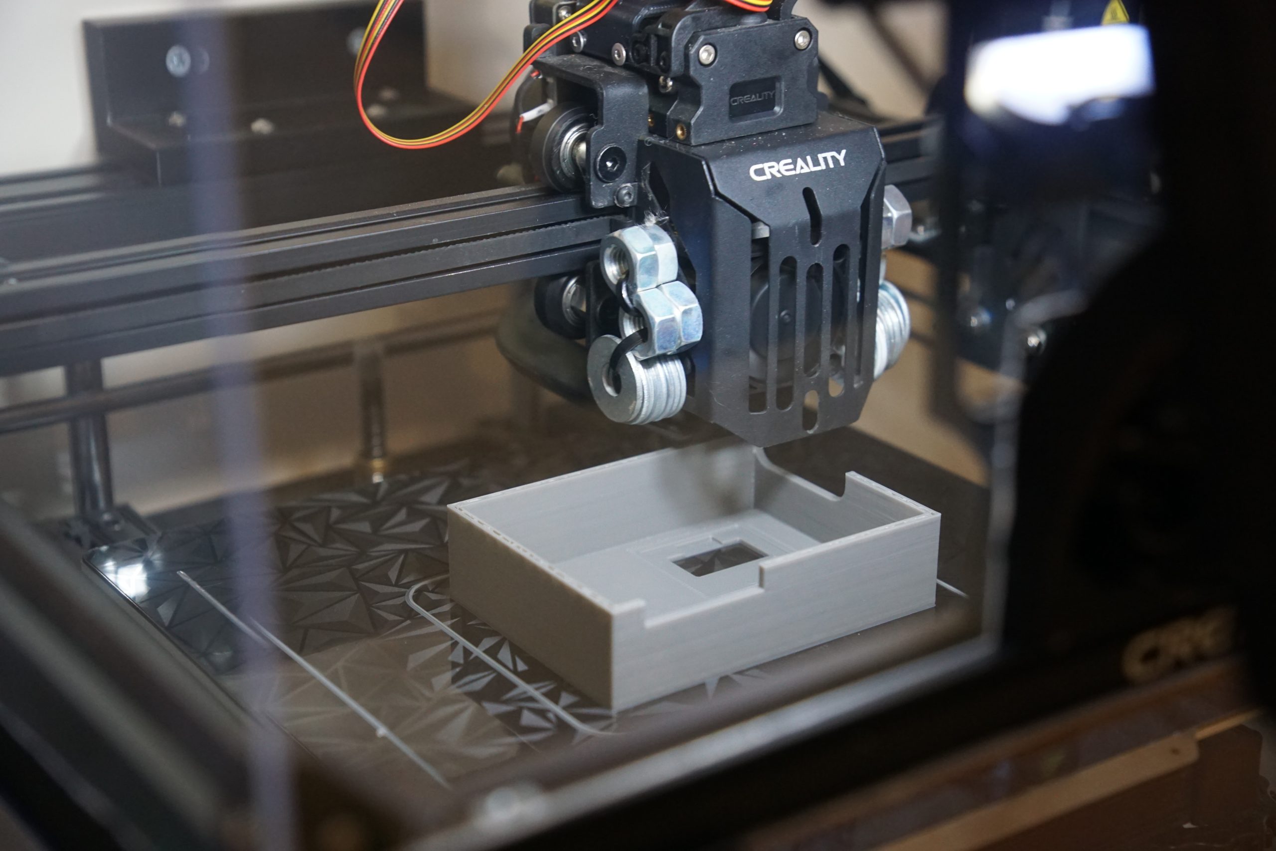
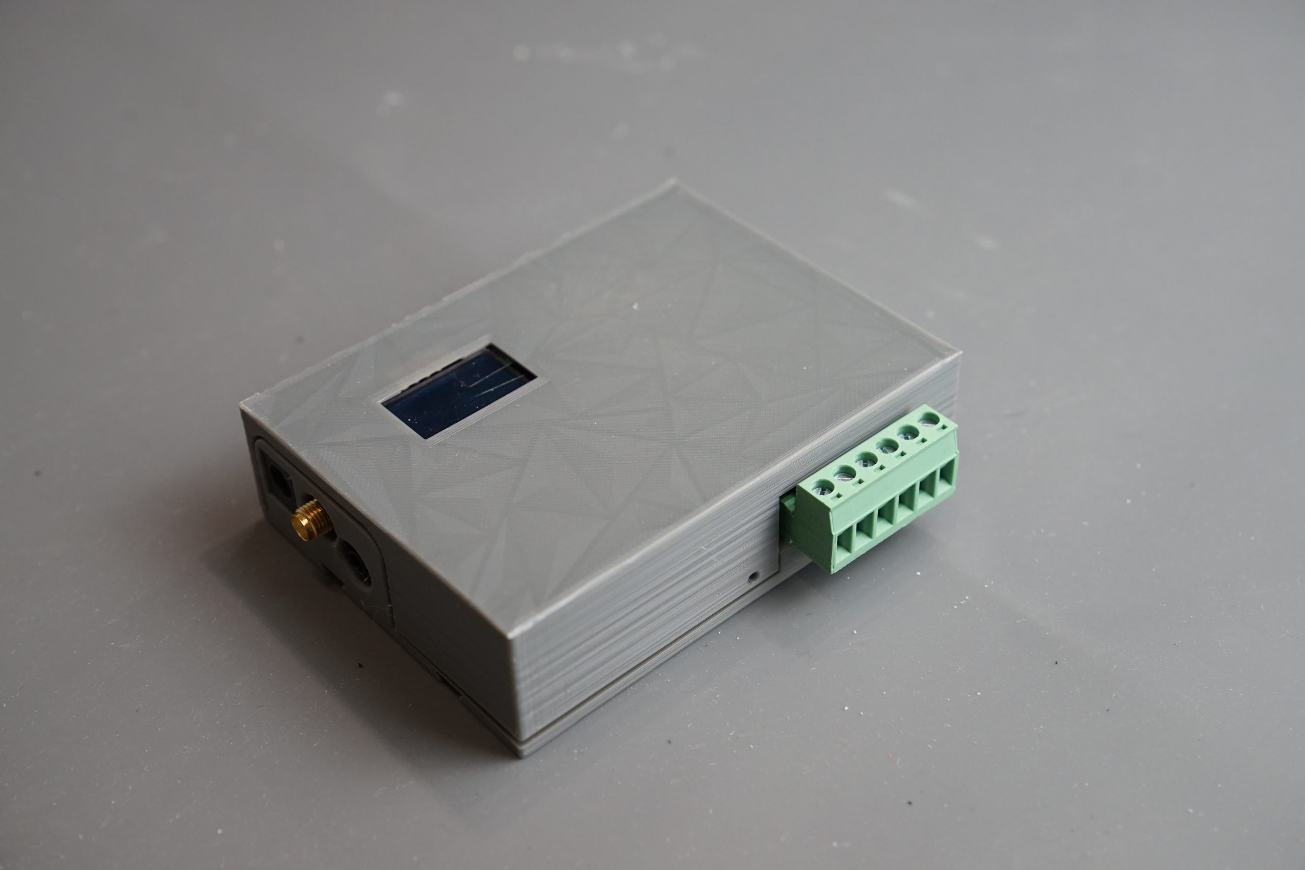
Thanks to the limited number of devices, the enclosure can be custom 3D-printed to fit the exact requirements of each application. The base version is printed in PETG, a material known for its higher melting point and resistance to chemicals, ideal for high-humidity, industrial environments.
The enclosure is designed to wrap around the core module, leaving connectors accessible for easy interfacing. It is composed of a top and bottom section that snap-fit together securely, providing both protection and ease of assembly without the need for screws or fasteners.
The module includes interchangeable accessories that allow for easy mounting on DIN rails, using cable ties or directly with holes and screws.
Remote control: GPRS, 3G and LTE
Unfortunately, despite European guidelines indicating GPRS availability until 2030, some Italian network operators have already begun decommissioning GPRS services. This presents a significant challenge, as our original communication module was based entirely on GPRS technology.
Thankfully, that choice was made purely to minimize costs by using ultra-low-budget GPRS-only modules. We can now pivot to more advanced LTE solutions, such as the SIM7600E, which not only provide modern network support but also run directly on 5V. This change enables us to remove the dedicated 4.8V 2A regulation circuitry, saving valuable PCB space and simplifying the power design. Not bad for a forced upgrade.
Of course, switching to LTE introduces a few new constraints. The LTE module requires high-speed communication, which necessitates using a hardware serial interface. However, the D1 module offers only one. Luckily, our modular design makes this transition manageable: we can simply create a new interface mask that mounts over the existing board, allowing us to switch to a more capable MCU like the ESP8266 and integrate the upgraded LTE module.
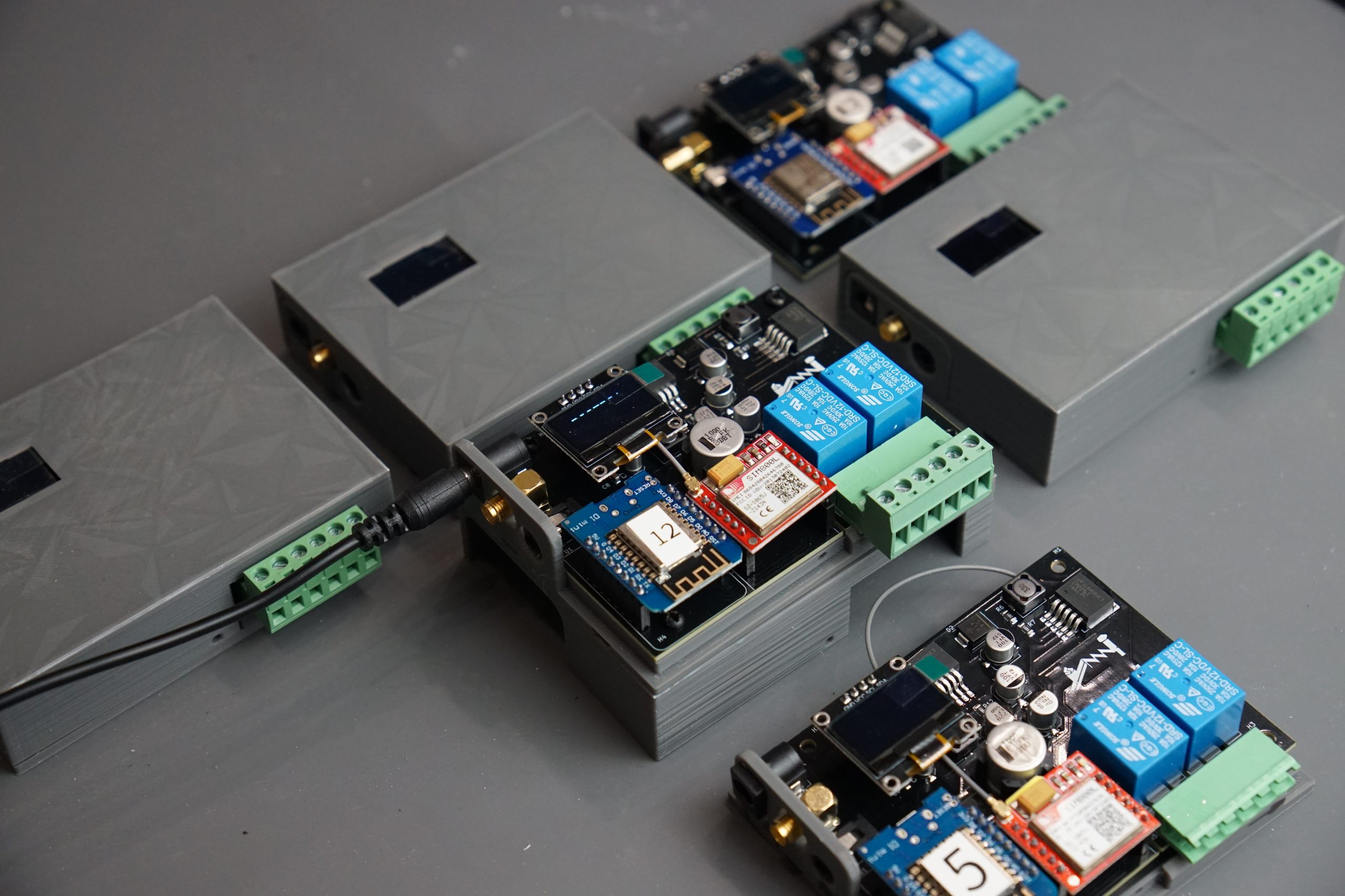
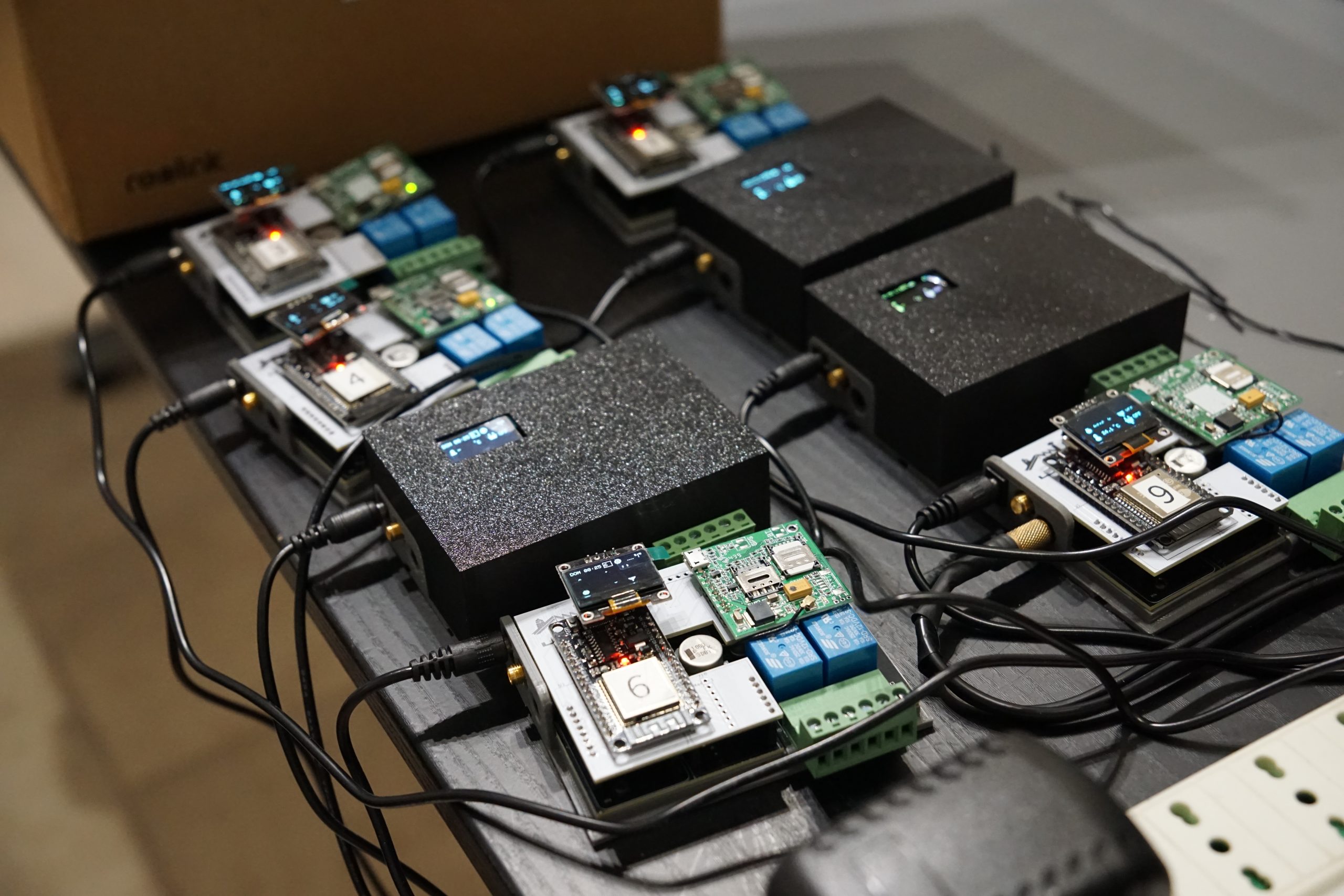
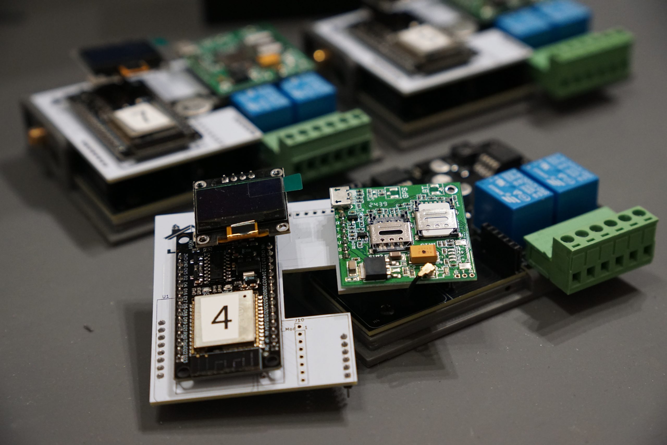
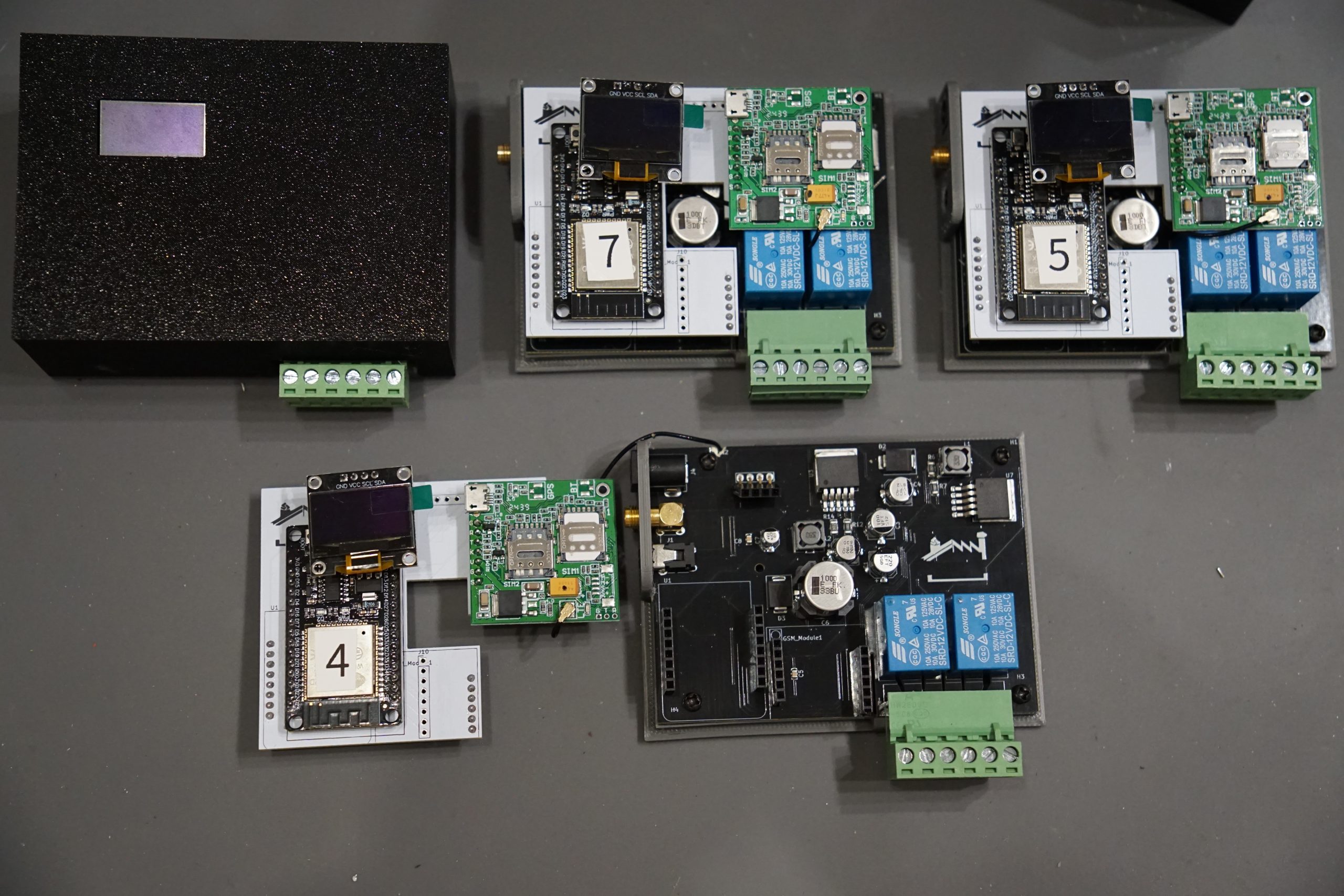
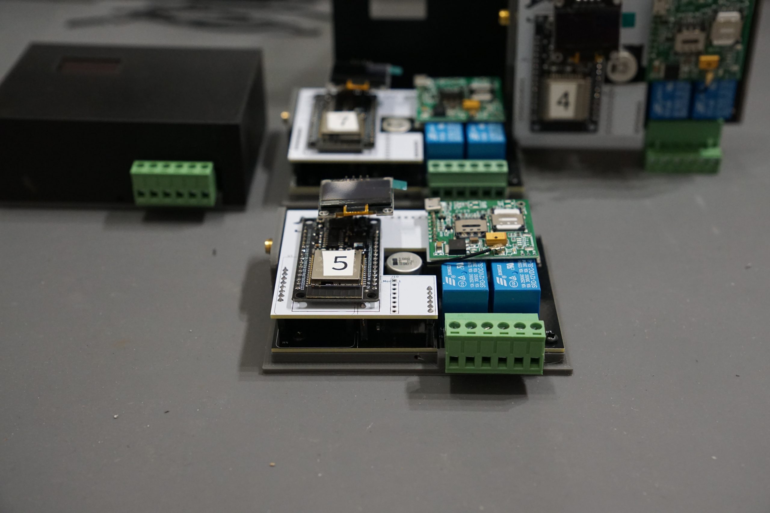
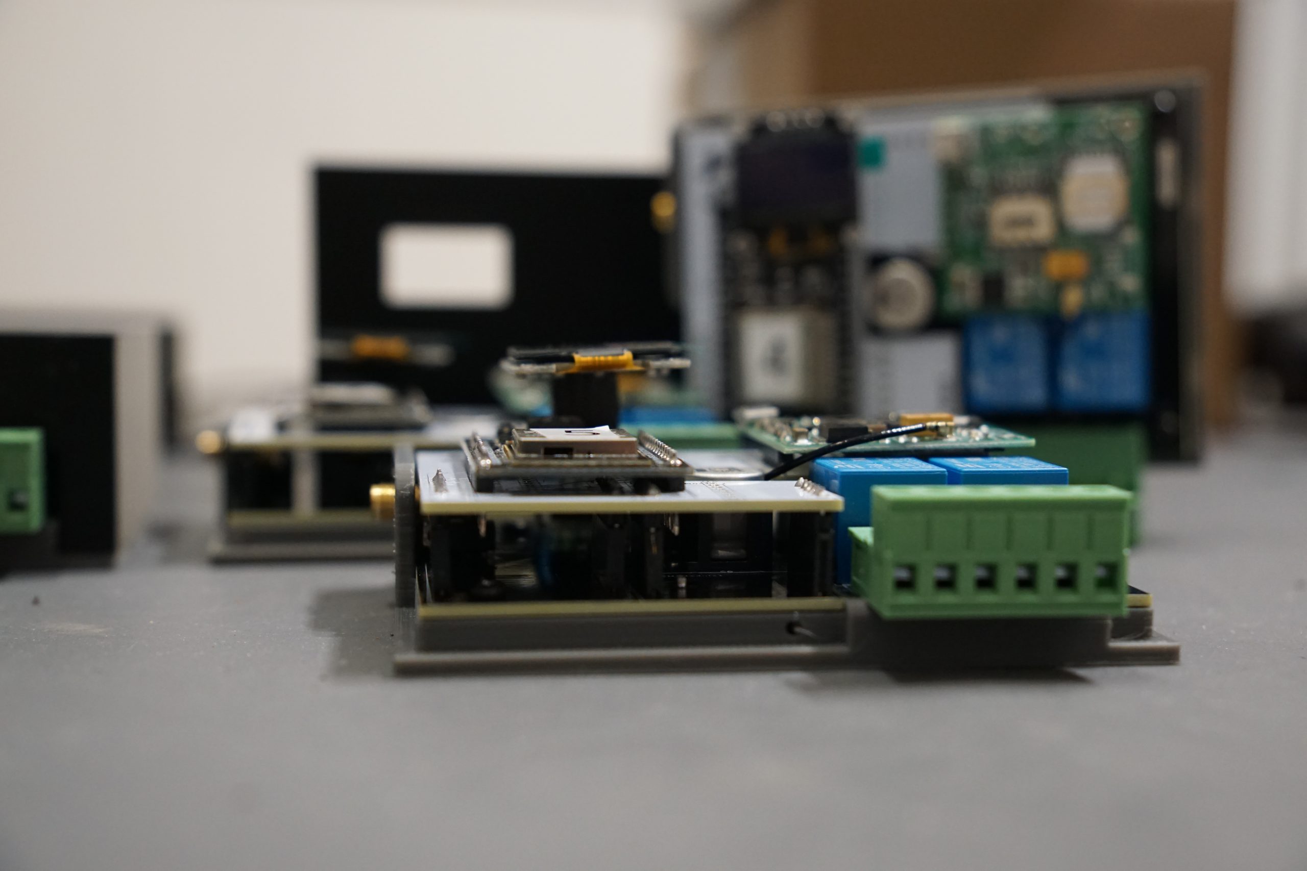
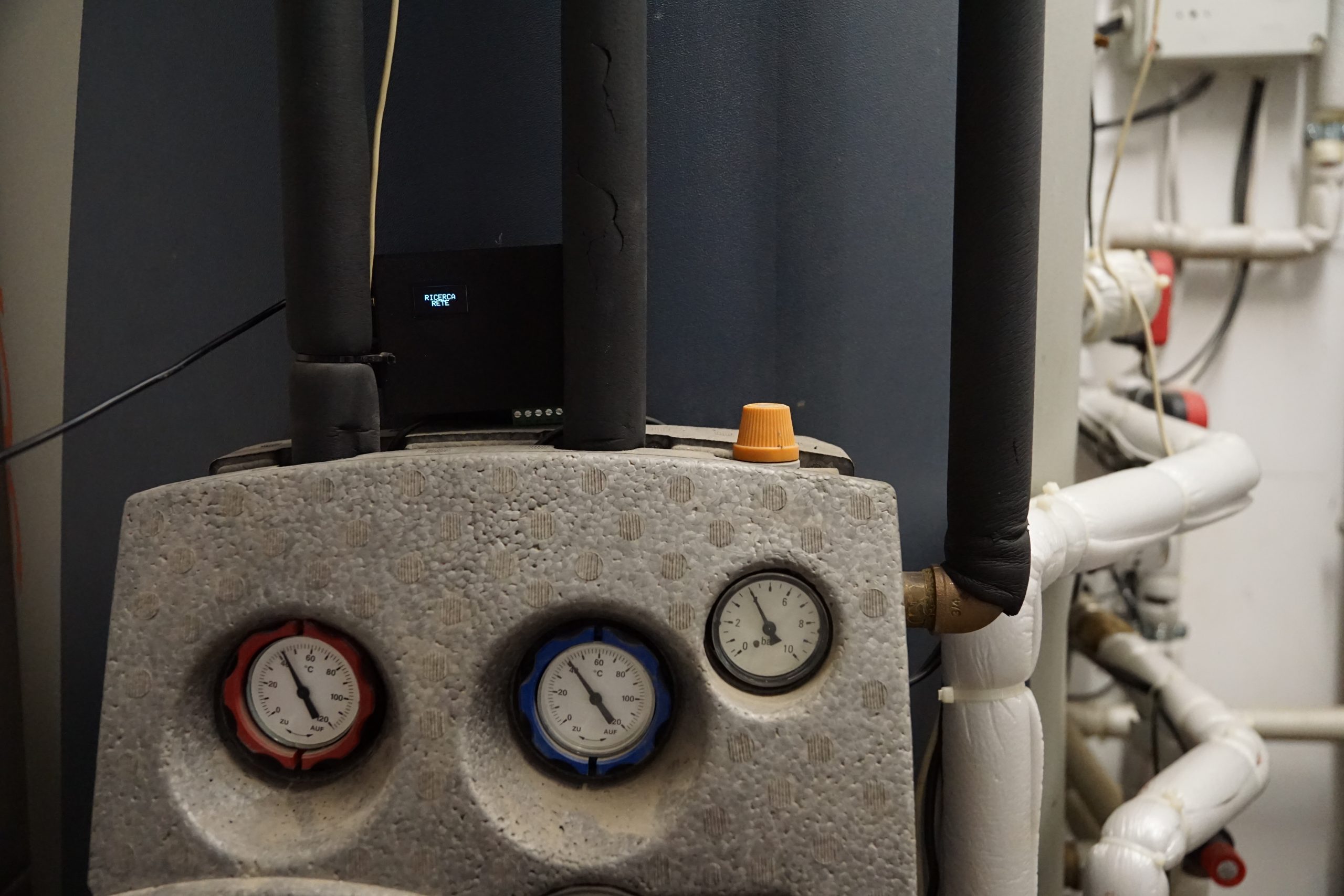
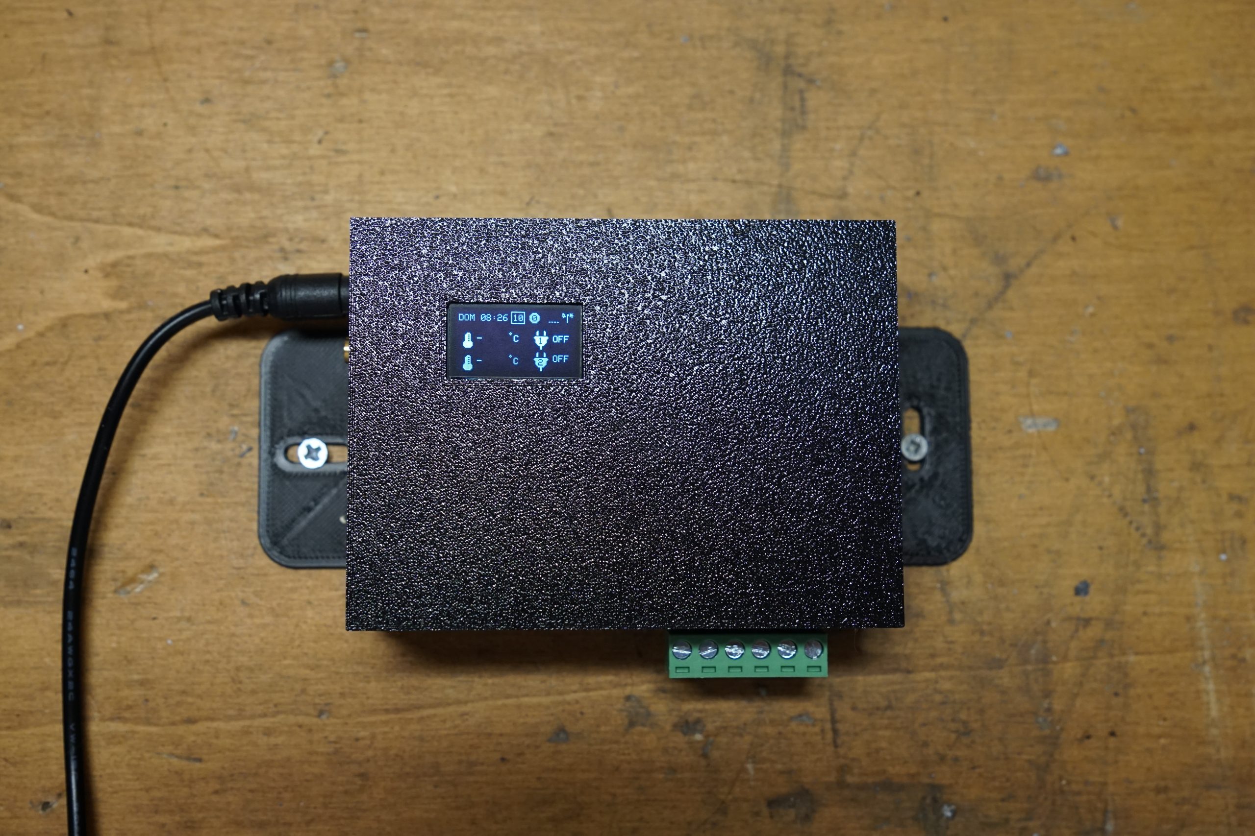
Interestingly, this upgrade brings a silver lining. The switch unlocks additional GPIOs on the new MCU, giving us greater flexibility to expand functionality. We can now easily integrate additional sensors, such as temperature, humidity, or other environmental probes, as well as more outputs. For instance, implementing an OpenTherm-compatible terminal for heating system control is now within reach.
All of these new features will be tested in a real-world application before moving ahead with a final, fully SMD-integrated prototype. The only downside remains cost: the LTE module has nearly quadrupled the price of the communication subsystem, now making up around 18% of the total device cost, still manageable given our limited production run of under 100 units.